Hardware
So far in this series I've looked at how you can get a computer to monitor temperatures. Now I'm going to look at the other side of the coin, and set about controlling the temperature. Specifically, this article will present a means to switch some fans on and off. Again I'm using the I²C bus, so this part of the project has acquired the name FanatIIC (Thanks to David Watkins for the suggestion). The circuits shown here could be set to work for other tasks though, so read on even if you've no need for anything that goes "whirr"...
This time we turn to the inventor of the I²C bus, Philips, for
the main component. The PCF8574 is an I²C 8-bit input / output expander.
Its pin-out is shown in figure 1. Besides the power and I²C bus pins,
there are the eight i/o pins, three sub-address pins and an interrupt pin (that
we'll not be using). The 3-bit binary code set on the sub-address pins allows
for up to eight 8574 chips to be used together on one bus. The occupied
I²C address range is &40 to &4F (the least significant bit denotes
read or write mode). Also there is a variation of this chip, the PCF8574A,
which is exactly the same, bar the use of a different address range. In this
case it uses from &70 to &7F, so you can have eight of these on your
bus as well. For now though, I'll be using just the one, for eight output bits.
Both the 8574 and the 8574A use a different address range to the DS1624
thermometers, and so will coexist happily.

To use the chip for 8-bit output it is simply a matter of writing the
output byte to the chip using the IIC_Control SWI. There is no control register for
setting the data direction. If you want to use any of the pins for input you
must first write those pins high, and then perform a read.
So, that's given us some digital outputs. But the 8574 on its own won't handle much current. Leafing through an electronics catalogue a few chips labelled as "motor drivers" leapt off the page. One of these, the L293D by Unitrode, seemed the obvious choice. This is a push-pull four channel driver. The output current rating is 600 mA per channel, at up to 36 V, which will handle medium-sized 12 V fans without difficulty. There is also an L293 model (no 'D') which has an even higher current rating, but has no output clamping diodes (see diodes page). The pin-out is shown in figure 1 also. There are several ways of wiring-up this chip. Each pair of outputs has an "inhibit" line, but I chose to keep all outputs active always, and just drive the individual input pins of two driver chips from the 8574.
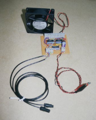
Figure 2 shows the main elements of the circuit. For clarity this shows only one of the two driver chips. The exact value for the pull-up resistors is not critical - something like 4k7 would be fine. The 0.1 mF capacitors from each 5 V supply pin (pin 16 on each device) to earth are for "decoupling". My first go at the circuit was on strip-board. This is pictured in figure 3. I've not drawn a diagram of the layout, as it's a bit of a mess with wire links everywhere. It's best left to your own skills if you want to try it this way. The three-pin device standing up from the board is a 7805 regulator, that provides 5 V to the three ICs. I chose to add this to give some autonomy to the board. You can set the outputs with the computer and then switch the computer off. The outputs will remain as set. Also I made provision for the regulator to supply the rest of the external I²C bus in place of the connection to the computer (don't connect the computer 5 V line as well!). That means one less line to the computer that could conduct a pulse from a lightning strike (ever the optimist!). The larger capacitors go from the +12 V and +5 V lines to earth for additional smoothing. I'm using a large (100 mF) electrolytic on the 12 V supply, in case there are any glitches caused by the output switching. I've used 2.2 mF on the 5 V pin, but whatever you can find in your junk box will probably do.
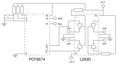
Figure 2. Part of the fan driver circuit. One L293D not shown. Repeat connections for other outputs.
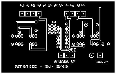
Having got the strip-board version to work I started on a PCB design. As before I used RiscPCB. The PCB file (and draw files) can be found on the download page, and is also shown in figure 4. It was looking like I'd need to add quite a few wire links, so I chose to use a double-sided design. With only basic PCB manufacturing facilities available (no "through-hole plating" and with alignment all done by hand) this can be a bit tricky. So you might prefer to adapt the layout to single-sided, replacing the component-side tracks with wire links. I used a photo-resist process, printing the pattern for each side onto inkjet transparency film. These are then used to mask the photo-sensitive etch resist when the PCB material is exposed to UV light. Once exposed this way, the board is developed and etched. The resulting board is pictured in figure 5. Be sure to align the component side accurately with the solder side - the holes in the pads must line-up! An alternative method I have read about, but not yet tried, uses a special film that can be printed-on directly in a LASER printer (or you can use a photocopier). This is then ironed onto plain copper-clad board and peeled off, leaving an etch-resistant mask.
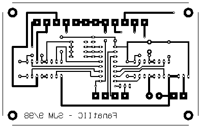
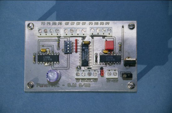
For my board to work I had to do some soldering on the component side as well as the solder side. It's pretty easy (I hope) to figure out where this is required. Solder the pads on all component-side tracks, all "vias" (where a wire link is made from one side to the other) and wherever the component-side earth plane meets a pin. In some cases this would be underneath a device, and inaccessible, so I provide a solder-side track and an adjacent via. The earth plane on the component side acts as a heat sink for the drivers. The four earth pins provide a good thermal connection, so I soldered these directly to the board, without using IC sockets. If you are driving a heavy load, or you used a single-sided board, you might need to add real heat sinks onto the driver chips.
A three-pin header carrying a link makes or breaks the +5 V connection to the I²C bus. I have made provision for an E-type fuse in the 12 V line. If you prefer you could replace this with a wire link and use an in-line fuse holder in your +12 V supply cable.
Be sure to give the board a thorough visual inspection before connecting it to anything. When you're happy connect it to your 12 V supply. Don't connect the computer yet. Use a multi-meter to check that the 5 V regulator circuit is working, and that the 0, +5 and +12 V pins around the board are all at the correct potentials. Check that there aren't any funny voltages on the I²C terminals. The power-up state of the 8574 is to switch on all outputs (beware of this if you plan to drive anything substantial, unattended - if there is a power interruption you can end up with everything running when you weren't expecting it), so check the output connections for +12 V with the multi-meter or connect some fans. If everything is well you can now switch off again, and connect the computer to the I²C bus terminals.
To check for correct operation of the hardware find the i2cio
program on the download page. This is a simple
command-line program for writing to or reading from devices on the I²C
bus. Whether it reads or writes depends upon the address used, as per the usual
I²C rule - read if bit 0 set. Supposing the 8574 has all its address bits
set to zero ("write" I²C address = &40 - for 8574A this would be
&70) the command to set all outputs high is:
i2cio 0x40 0xFF
To set all outputs low:
i2cio 0x40 0x00
Using these commands check that all outputs toggle state correctly.